Behavior path planner path generation
Path Generation#
This document explains how the path is generated for lane change and avoidance, etc. The implementation can be found in path_shifter.hpp.
Overview#
The base idea of the path generation in lane change and avoidance is to smoothly shift the reference path, such as the center line, in the lateral direction. This is achieved by using a constant-jerk profile as in the figure below. More details on how it is used can be found in README. It is assumed that the reference path is smooth enough for this algorithm.
The figure below explains how the application of a constant lateral jerk l^{'''}(s) can be used to induce lateral shifting. In order to comply with the limits on lateral acceleration and velocity, zero-jerk time is employed in the figure ( T_a and T_v ). In each interval where constant jerk is applied, the shift position l(s) can be characterized by a third-degree polynomial. Therefore the shift length from the reference path can then be calculated by combining spline curves.
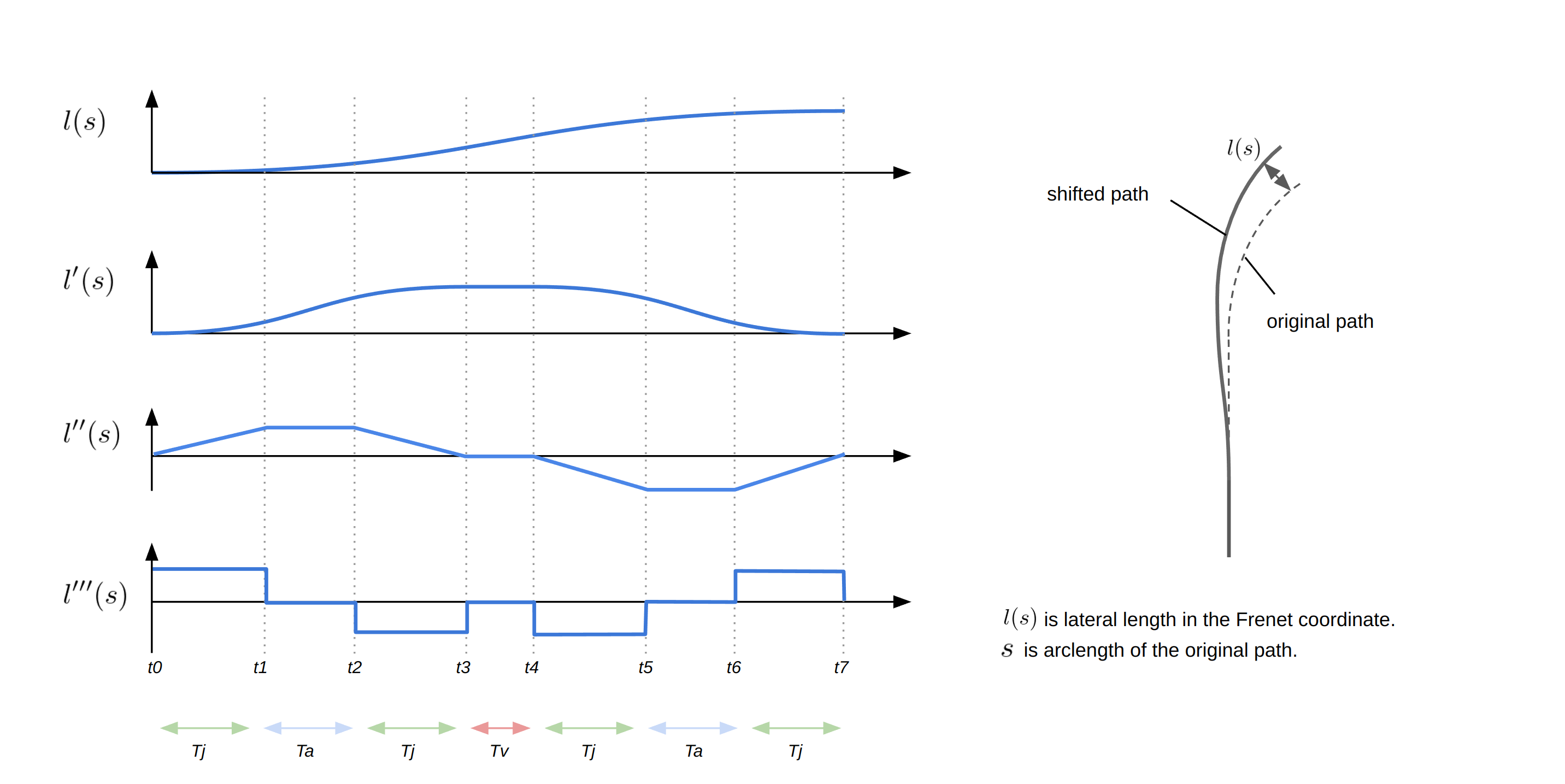
Note that, due to the rarity of the T_v in almost all cases of lane change and avoidance, T_v is not considered in the current implementation.
Mathematical Derivation#
By applying simple integral operations, the following analytical equations can be derived to describe the shift distance l(t) at each time under lateral jerk, acceleration, and velocity constraints.
\begin{align}
l_1&= \frac{1}{6}jT_j^3\\[10pt]
l_2&= \frac{1}{6}j T_j^3 + \frac{1}{2} j T_a T_j^2 + \frac{1}{2} j T_a^2 T_j\\[10pt]
l_3&= j  T_j^3 + \frac{3}{2} j T_a T_j^2 + \frac{1}{2} j T_a^2 T_j\\[10pt]
l_4&= j T_j^3 + \frac{3}{2} j T_a T_j^2 + \frac{1}{2} j T_a^2 T_j + j(T_a + T_j)T_j T_v\\[10pt]
l_5&= \frac{11}{6} j T_j^3 + \frac{5}{2} j T_a T_j^2 + \frac{1}{2} j T_a^2 T_j + j(T_a + T_j)T_j T_v \\[10pt]
l_6&= \frac{11}{6} j T_j^3 + 3 j T_a T_j^2 + j T_a^2 T_j + j(T_a + T_j)T_j T_v\\[10pt]
l_7&= 2 j T_j^3 + 3 j T_a T_j^2 + j T_a^2 T_j + j(T_a + T_j)T_j T_v
\end{align}
These equations are used to determine the shape of a path. Additionally, by applying further mathematical operations to these basic equations, the expressions of the following subsections can be derived.
Calculation of Maximum Acceleration from transition time and final shift length#
In the case where there are no limitations on lateral velocity and lateral acceleration, the maximum lateral acceleration during the shifting can be calculated as follows. The constant-jerk time is given by T_j = T_{\rm total}/4 because of its symmetric property. Since T_a=T_v=0, the final shift length L=l_7=2jT_j^3 can be determined using the above equation. The maximum lateral acceleration is then given by a_{\rm max} =jT_j. This results in the following expression for the maximum lateral acceleration:
\begin{align}
a_{\rm max}  = \frac{8L}{T_{\rm total}^2}
\end{align}
Calculation of Ta, Tj and jerk from acceleration limit#
In the case where there are no limitations on lateral velocity, the constant-jerk and acceleration times, as well as the required jerk can be calculated from the acceleration limit, total time, and final shift length as follows. Since T_v=0, the final shift length is given by:
\begin{align}
L = l_7 = 2 j T_j^3 + 3 j T_a T_j^2 + j T_a^2 T_j
\end{align}
Additionally, the velocity profile reveals the following relations:
\begin{align}
a_{\rm lim} &= j T_j\\
T_{\rm total} &= 4T_j + 2T_a
\end{align}
By solving these three equations, the following can be obtained:
\begin{align}
T_j&=\frac{T_{\rm total}}{2} - \frac{2L}{a_{\rm lim} T_{\rm total}}\\[10pt]
T_a&=\frac{4L}{a_{\rm lim} T_{\rm total}} - \frac{T_{\rm total}}{2}\\[10pt]
jerk&=\frac{2a_{\rm lim} ^2T_{\rm total}}{a_{\rm lim} T_{\rm total}^2-4L}
\end{align}
where T_j is the constant-jerk time, T_a is the constant acceleration time, j is the required jerk, a_{\rm lim} is the acceleration limit, and L is the final shift length.
Calculation of Required Time from Jerk and Acceleration Constraint#
In the case where there are no limitations on lateral velocity, the total time required for shifting can be calculated from the jerk and acceleration limits and the final shift length as follows. By solving the two equations given above:
L = l_7 = 2 j T_j^3 + 3 j T_a T_j^2 + j T_a^2 T_j,\quad a_{\rm lim} = j T_j
we obtain the following expressions:
\begin{align}
T_j &= \frac{a_{\rm lim}}{j}\\[10pt]
T_a &= \frac{1}{2}\sqrt{\frac{a_{\rm lim}}{j}^2 + \frac{4L}{a_{\rm lim}}} - \frac{3a_{\rm lim}}{2j}
\end{align}
The total time required for shifting can then be calculated as T_{\rm total}=4T_j+2T_a.
Limitation#
- Since T_v is zero in almost all cases of lane change and avoidance, T_v is not considered in the current implementation.