Hardware and calibration
Choosing a camera, mounting it on the vehicle, and computing the homography that lets Vision Pilot measure the road from a single image.
Running Vision Pilot on your own vehicle takes three things: the right camera, mounted correctly, and calibrated. Get any of the three wrong and the stack will mis-measure the road and every distance it reports.
Choosing a camera
The baseline specification is a single automotive-grade camera:
| Property | Specification |
|---|---|
| Interface | GMSL2 (recommended) |
| Type | RGB, monocular |
| Resolution | 2 MP (1-2 MP supported) |
| Horizontal FoV | 50-55° |
| Frame rate | 10 Hz design cadence |
| Count | One, front-facing |
| Compute budget | ~3-5 INT8 TOPs for the full stack |
Do not use a wide-angle camera. Wider fields of view lack the ability to resolve the scene at long range, which is exactly what highway driving and ADAS safety features depend on. This is a hard requirement, not a preference.
Why 10 Hz is enough
Vision Pilot is designed to run at 10 Hz. You can run it faster, but there is little reason to: an average human driver has a reaction time equivalent to about 4 Hz, and an F1 driver about 8 Hz. At 10 Hz Vision Pilot already reacts faster than any human, with compute headroom left over.
Mounting the camera
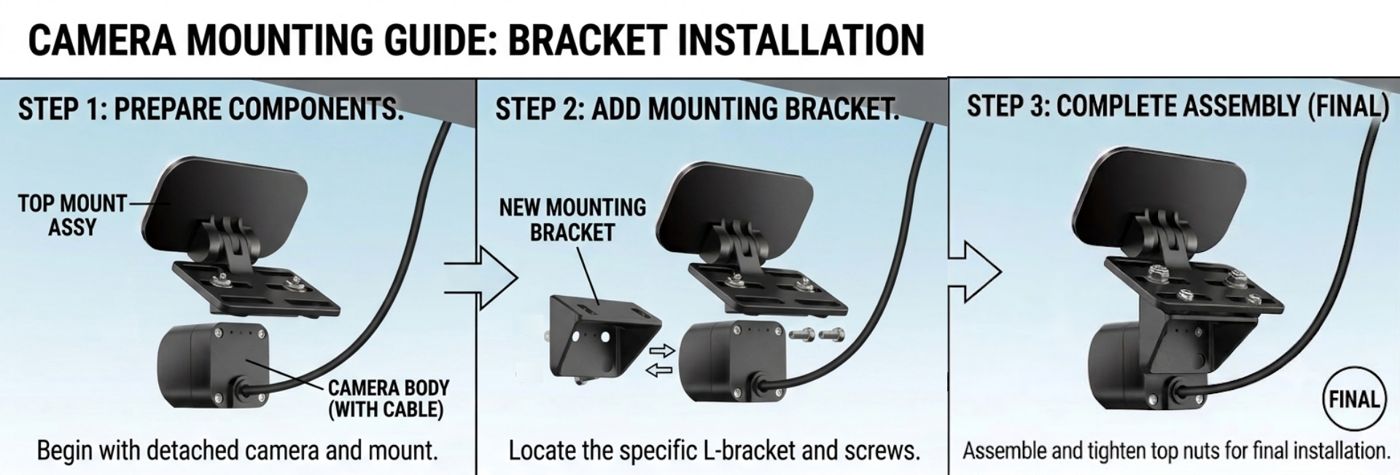
Mount the camera behind the front windscreen, underneath the rear-view mirror - the same place automotive OEMs put their stock ADAS cameras.
| Axis | Target |
|---|---|
| Roll | 0° - the camera must be level |
| Yaw | Along the vehicle centreline, facing forward |
| Pitch | 1-3° down for passenger cars |
| Pitch | 10-15° down for taller vehicles - shuttles, buses, trucks |
Physical mounting
Most automotive GMSL evaluation cameras have screw holes on the back face for mounting to a body frame. The recommended approach:
- Screw an L-bracket into the mounting holes on the back face of the camera.
- Screw that bracket into the mounting plate of a windscreen mount - the Pixelman camera mount works well, despite being sold for rear windscreens.
- Adhere the mount to the front windscreen in the position above.
The mount must be rigid. If the camera shifts after calibration, the homography is invalid and every distance measurement is wrong - you will have to calibrate again.
Calibration
Vision Pilot measures the road in metres from a single camera. That is only possible because it knows the homography matrix H - the 3×3 mapping from image pixels (u, v) to flat road coordinates (X, Y):
[ X ]        [ u ]
[ Y ]   ~  H [ v ]
[ 1 ]        [ 1 ]
The Calibration/ folder contains
calc_front_camera_homography.py, which computes H from a single photograph of four
checkerboard markers on the ground.
Coordinate convention
Origin is at the centre of the front bumper, on the ground. X is positive forward, Y is positive left.
1. Lay out the ground markers
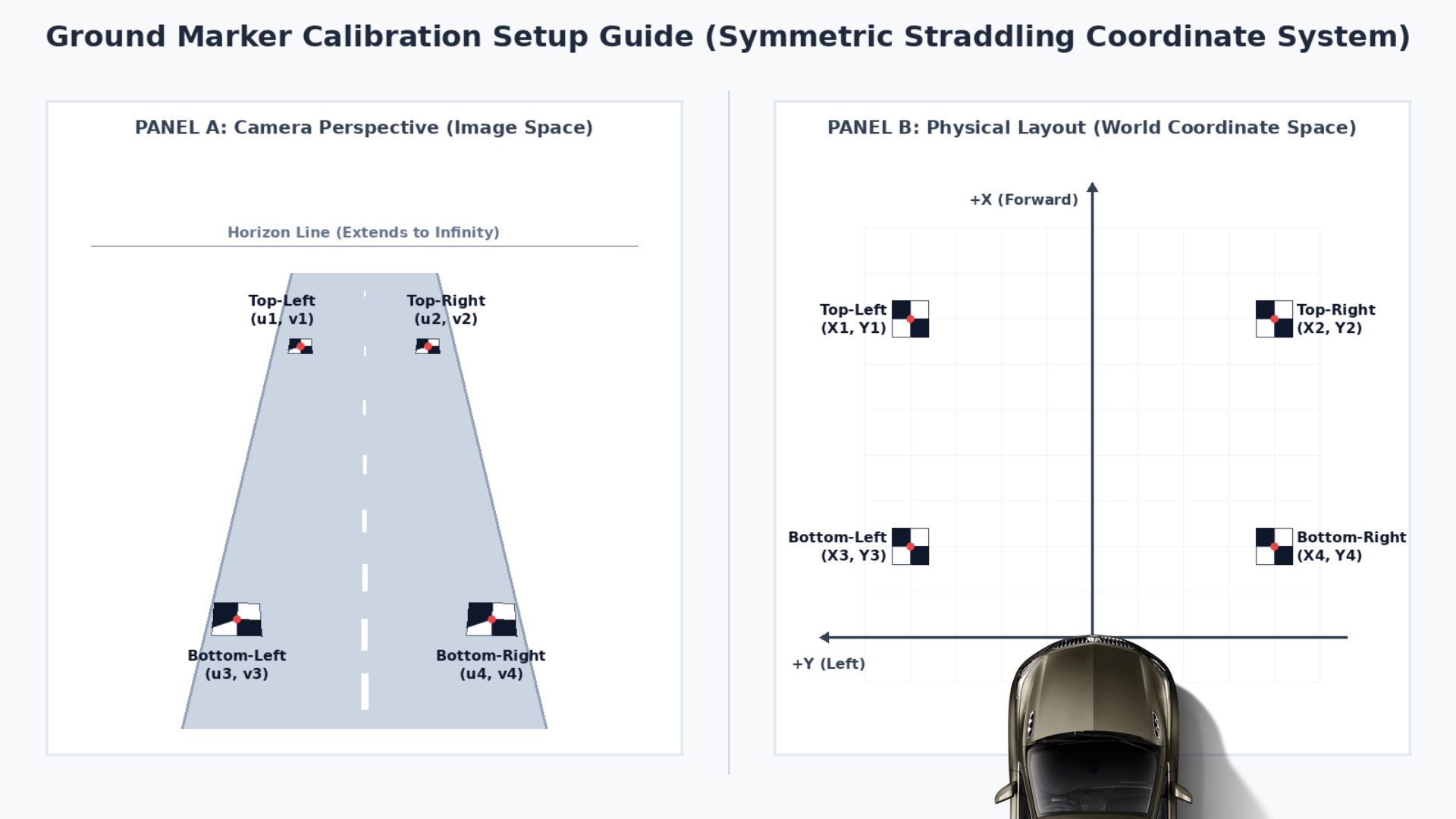
- Print four copies of the checkerboard pattern, one 2×2 board per A4 page. A 2×2 board is two black and two white squares meeting at a single point - that centre intersection is the pixel-accurate coordinate the script detects.
- Tape all four flat to the asphalt in front of the vehicle, in a rectangle, all visible to the camera. They must not slide or warp.
- Measure the distance from the bumper-centre origin to each board’s centre, and record which board is which - top-left, top-right, bottom-left, bottom-right.

| Marker | Image coordinate | World coordinate |
|---|---|---|
| Top-left | ($u_1$, $v_1$) | ($X_1$, $Y_1$) |
| Top-right | ($u_2$, $v_2$) | ($X_2$, $Y_2$) |
| Bottom-left | ($u_3$, $v_3$) | ($X_3$, $Y_3$) |
| Bottom-right | ($u_4$, $v_4$) | ($X_4$, $Y_4$) |
2. Capture the calibration image
Save one frame from the mounted camera showing all four checkerboards on the road. Make sure the camera is rigidly fixed - if it moves after this point, start over.
3. Run the script
cd Calibration

python calc_front_camera_homography.py \
  --img road_frame.jpg \
  --out ../VisionPilot/config/H.yaml \
  --tl 0.0 15.0 \
  --tr 3.7 15.0 \
  --bl 0.0 0.0 \
  --br 3.7 0.0
| Argument | Meaning |
|---|---|
--img |
Path to the captured calibration image |
--out |
Where to write the homography - target VisionPilot/config/H.yaml |
--tl |
Top-left marker world coordinates: X (depth), Y (offset) |
--tr |
Top-right marker world coordinates |
--bl |
Bottom-left marker world coordinates |
--br |
Bottom-right marker world coordinates |
Keep a copy of the original H.yaml. It matches the sample dataset, so retaining it lets you
keep running the sample sequences after switching to your own camera.
4. Verify the result
The script writes <your_out_name>_visualization.png alongside the matrix. Open it and check:
- Green lines - a uniform physical grid projected back onto the perspective image. If the calibration is accurate they run parallel to the real road lines and compress correctly toward the horizon.
- Red circles - the detected checkerboard centres, labelled with their assignment. Confirm each label matches the board you measured.
If the green grid does not lie flat along the road, the calibration is wrong. Do not proceed.
How the script works
- Sub-pixel corner extraction -
cv2.findChessboardCornerswith pattern size(1,1)locates each 2×2 intersection, refined bycv2.cornerSubPix. - Iterative detection with masking - after locating one board, its region is masked out with
a white circle of radius
max(width, height)/20, so the next iteration finds a different board. - Spatial sorting - points are sorted vertically into top/bottom rows by v, then horizontally into left/right by u.
- Homography solve - OpenCV’s Direct Linear Transform, written out as an OpenCV
FileStorageYAML. - Inverse backprojection - $H^{-1}$ projects a uniform world-coordinate grid back into image space for the verification overlay.
Calibration troubleshooting
No corners found. Get high-contrast, even illumination on the road. A shadow falling across a
checkerboard will defeat corner detection. On reflective pavement, adjust the
cv2.findChessboardCorners flags.
Left/right markers swapped. The spatial sort assumes minimal camera roll. Tilt beyond about 45° breaks the left-right pairing. Keep the camera level.
Grid lines shooting into the sky. Lines projected past the horizon can wrap around
mathematically. The script clips these with a perspective-depth filter
(homog_img[:, 2] > 1e-5); if you still see it, your marker coordinates are likely mismeasured.
Vehicle parameters
Once calibrated, set the wheelbase in config/vision_pilot.conf - the lateral controller uses it
directly:
L = 2.860 # front axle to CoG (m), where L = Lf + Lr
And check the CAN database in config/vehicle.dbc matches your vehicle’s bus.
See configuration for the rest.