Autoware Trajectory#
This package provides classes to manage/manipulate Trajectory.
Overview#
Interpolators#
The interpolator class interpolates given bases and values. Following interpolators are implemented.
- Linear
- AkimaSpline
- CubicSpline
- NearestNeighbor
- Stairstep

The builder internally executes interpolation and return the result in the form of expected<T, E>. If successful, it contains the interpolator object.
  std::vector<double> xs = {0.0, 1.0, 2.0, 3.0, 4.0, 5.0};
  std::vector<double> ys = {0.0 + noise(), 1.0 + noise(), 2.0 + noise(),
                            3.0 + noise(), 4.0 + noise(), 5.0 + noise()};

  // You need to use the `Builder` to try to construct the interpolator
  const tl::expected<CubicSpline, InterpolationFailure> result =
    CubicSpline::Builder()
      .set_bases(xs)   // set the base
      .set_values(ys)  // set the value
      .build();        // finally, call build()

  // The result may be `InterpolationFailure` type if the input is not suitable
  // for this interpolator
  if (!result) {
    return 0;
  }
Otherwise it contains the error object representing the failure reason. In the below snippet, cubic spline interpolation fails because the number of input points is 3, which is below the minimum_required_points() = 4 of CubicSpline.
  // Give only 3 points for CubicSpline, which is infeasible
  std::vector<double> xs = {0.0, 1.0, 2.0};
  std::vector<double> ys = {0.0 + noise(), 1.0 + noise(), 2.0 + noise()};

  // You need to use the `Builder` to try to construct the interpolator
  const tl::expected<CubicSpline, InterpolationFailure> result =
    CubicSpline::Builder()
      .set_bases(xs)   // set the base
      .set_values(ys)  // set the value
      .build();        // finally, call build()
In such cases the result expected object contains InterpolationFailure type with an error message like "base size 3 is less than minimum required 4".
For Linear, CubicSpline, AkimaSpline, and SphericalLinear, consecutive input points whose base difference is smaller than the interpolator epsilon are automatically removed as duplicates before interpolation. The default spatial builders use k_epsilon_distance, while temporal time-base handling uses k_epsilon_time. If the cleaned number of points falls below minimum_required_points(), the build fails and falls back to the next candidate interpolator when build_with_fallback is used.
Trajectory class#
The Trajectory class provides mathematical continuous representation and object oriented interface for discrete array of following point types
-
geometry_msgs::Point -
geometry_msgs::Pose -
autoware_planning_msgs::PathPoint -
autoware_planning_msgs::PathPointWithLaneId -
autoware_planning_msgs::TrajectoryPoint
by interpolating the given underlying points. Once built, arbitrary point on the curve is continuously parametrized by a single s coordinate.
  std::vector<geometry_msgs::msg::Point> underlying_points = {
    pose(0.49, 0.59), pose(1.20, 2.56), pose(1.51, 3.17), pose(1.85, 3.76),
    pose(2.60, 4.56), pose(3.61, 4.30), pose(3.95, 4.01), pose(4.90, 3.25),
    pose(5.54, 3.10), pose(6.88, 3.54), pose(7.85, 4.93), pose(8.03, 5.73),
    pose(8.16, 6.52), pose(8.68, 8.45), pose(8.96, 8.96), pose(9.32, 9.36)};
  auto result = Trajectory<geometry_msgs::msg::Point>::Builder{}.build(underlying_points);
  if (!result) {
    std::cout << result.error().what << std::endl;
    return 0;
  }
  auto & trajectory = result.value();
  const auto s = trajectory.base_arange(0.05);  // cppcheck-suppress shadowVariable
  const auto C = trajectory.compute(s);
Nomenclature#
This section introduces strict definition of several words used in this package to clarify the description of API and help the developers understand and grasp the geometric meaning of algorithms.
| Word | Meaning | Illustration |
|---|---|---|
curve |
curve is an oriented bounded curve denoted as (x(s), y(s), z(s)) with additional properties, parameterized by s (s = 0 at the start). |
 View in Drawio There are 5 underlying points\(\mathrm{P0} = (0, 0, 0)\) \(\mathrm{P1} = (1/ \sqrt{2}, 1/ \sqrt{2}, 0)\) \(\mathrm{P2} = (1/ \sqrt{2}, 1+1/ \sqrt{2}, 0)\) \(\mathrm{P3} = (2/ \sqrt{2}, 1+2/ \sqrt{2}, 0)\) \(\mathrm{P4} = (2/ \sqrt{2} + 1/ \sqrt{6}, 1+2/ \sqrt{2} + 1 / \sqrt{3}, 1 / \sqrt{2})\) and the arc length between each interval is \(1, 2, 1, 1\) respectively, so \(\mathrm{start} = 0\) and \(\mathrm{end} = 5\). |
underlying |
underlying points of a curve refers to the list of 3D points from which the curve was interpolated. |
|
arc length[m] |
arc length denotes the approximate 3D length of of a curve and is computed based on the discrete underlying points. |
|
s[m] |
s denotes the 3D arc length coordinate starting from the base point (mostly the start point) of the curve and a point is identified by trajectory(s).Due to this definition, the actual curve length and arc length have subtle difference as illustrated. |
 View in Drawio The point for \(s = 0.5\) is the purple dot, but the curve length from \(\mathrm{P0}\) to this point does not equal to \(0.5\). The exact curve length is \(\int \sqrt{(\frac{dx}{dt})^2 + (\frac{dy}{dt})^2 + (\frac{dz}{dt})^2} dt\), which cannot be obtained in an analytical closed form. |
curvature |
curvature is computed using only X-Y 2D coordinate. This is based on the normal and natural assumption that roads are flat. Mathematically, it asserts that Gaussian curvature of road is uniformly 0.The sign of curvature is positive if the center of turning circle is on the left side, otherwise negative. |
 View in Drawio |
k_epsilon_distance |
Distance epsilon used for spatial duplicate handling and geometric almost-same checks. |
|
k_epsilon_time |
Time epsilon used for temporal duplicate handling in time-parameterized utilities. | |
almost-same |
The pair of two points \(P_{1}\) and \(P_{2}\), the pair of two base values \(s_{1}\) and \(s_{2}\), or the pair of two quaternions are called almost-same if their distance, difference, or represented rotation difference are less than the corresponding epsilon for that quantity. |
API#
Interpolators#
| Class | Method/Function | Description |
|---|---|---|
| Common Functions | minimum_required_points() |
return the number of points required for each concrete interpolator |
compute(double s) -> T |
compute the interpolated value at given base \(s\). \(s\) is clamped to the underlying base range. | |
compute(vector<double> s) -> vector<T> |
compute the interpolated values at for each base values in \(s\). | |
compute_first_derivative(double s) -> double |
compute the first derivative of at given base \(s\). \(s\) is clamped. | |
compute_second_derivative(double s) -> double |
compute the second derivative of at given base \(s\). \(s\) is clamped. |
AkimaSpline requires at least 5 points to interpolate.
  std::vector<double> xs = {0.0, 1.0, 2.0, 3.0, 4.0, 5.0};
  std::vector<double> ys = {0.0 + noise(), 1.0 + noise(), 2.0 + noise(),
                            3.0 + noise(), 4.0 + noise(), 5.0 + noise()};

  // You need to use the `Builder` to try to construct the interpolator
  const tl::expected<AkimaSpline, InterpolationFailure> result =
    AkimaSpline::Builder()
      .set_bases(xs)   // set the base
      .set_values(ys)  // set the value
      .build();        // finally, call build()
  const auto & trajectory = result.value();

CubicSpline requires at least 4 points to interpolate.
  std::vector<double> xs = {0.0, 1.0, 2.0, 3.0, 4.0, 5.0};
  std::vector<double> ys = {0.0 + noise(), 1.0 + noise(), 2.0 + noise(),
                            3.0 + noise(), 4.0 + noise(), 5.0 + noise()};

  // You need to use the `Builder` to try to construct the interpolator
  const tl::expected<CubicSpline, InterpolationFailure> result =
    CubicSpline::Builder()
      .set_bases(xs)   // set the base
      .set_values(ys)  // set the value
      .build();        // finally, call build()

Linear requires at least 2 points to interpolate.
  std::vector<double> xs = {0.0, 1.0, 2.0, 3.0, 4.0, 5.0};
  std::vector<double> ys = {0.0 + noise(), 1.0 + noise(), 2.0 + noise(),
                            3.0 + noise(), 4.0 + noise(), 5.0 + noise()};

  // You need to use the `Builder` to try to construct the interpolator
  const tl::expected<Linear, InterpolationFailure> result = Linear::Builder()
                                                              .set_bases(xs)   // set the base
                                                              .set_values(ys)  // set the value
                                                              .build();  // finally, call build()

StairStep requires at least 2 points to interpolate.
  std::vector<double> xs = {0.0, 1.0, 2.0, 3.0, 4.0, 5.0};
  std::vector<double> ys = {0.0 + noise(), 1.0 + noise(), 2.0 + noise(),
                            3.0 + noise(), 4.0 + noise(), 5.0 + noise()};

  // You need to use the `Builder` to try to construct the interpolator
  const tl::expected<Stairstep<double>, InterpolationFailure> result =
    Stairstep<double>::Builder()
      .set_bases(xs)   // set the base
      .set_values(ys)  // set the value
      .build();        // finally, call build()

Example of custom Interpolator usage#
You can also specify interpolation method to Builder{} before calling .build(points)
```cpp using autoware::experimental::trajectory::interpolator::CubicSpline;
std::optional
Trajectory class#
Several Trajectory<T> are defined in the following inheritance hierarchy according to the sub object relationships.

Each derived class in the diagram inherits the methods of all of its descending subclasses. For example, all of the classes have the methods like length(), curvature() in common.
<autoware/trajectory/point.hpp>#
| Class | Method | Description | Illustration |
|---|---|---|---|
|
Builder() |
set default interpolator setting as follows.
|
|
set_xy_interpolator<InterpolatorType>() |
set custom interpolator for x, y. |
||
set_z_interpolator<InterpolatorType>() |
set custom interpolator for z. |
||
build(const vector<Point> &) |
return expected<Trajectory<Point>, InterpolationFailure> object. |
||
|
base_arange(const double step) |
return vector of s values starting from start, with the interval of step, including end. Thus the return value has at least the size of 2. |
|
length() |
return the total arc length of the trajectory. |
View in Drawio length() is \(5.0\) because it computes the sum of the length of dotted lines. |
|
azimuth(const double s) |
return the tangent angle at given s coordinate using std::atan2. |
 View in Drawio |
|
curvature(const double s) |
return the signed curvature at given s coordinate following \(\sqrt{\dot{x}^2 + \dot{y}^2}^3 / (\dot{x}\ddot{y} - \dot{y}\ddot{x})\). |
See above | |
elevation(const double s) |
return the elevation angle at given s coordinate. |
||
get_underlying_base() |
return the vector of s values of current underlying points. |
<autoware/trajectory/pose.hpp>#
| Class | Method | Description | Illustration |
|---|---|---|---|
|
Builder() |
set default interpolator setting in addition to that of Trajectory<Point>::Builder as follows.
|
|
set_orientation_interpolator<InterpolatorType>() |
set custom interpolator for orientation. |
||
build(const vector<Pose> &) |
return expected<Trajectory<Pose>, InterpolationFailure> object. |
||
|
derives all of the above methods of Trajectory<Point> |
||
align_orientation_with_trajectory_direction() |
update the underlying points so that their orientations match the azimuth() of interpolated curve. This is useful when the user gave only the position of Pose and created Trajectory object. |
 View in Drawio |
<autoware/trajectory/path_point.hpp>#
| Class | Method | Description | Illustration |
|---|---|---|---|
|
Builder() |
set default interpolator setting in addition to that of Trajectory<Pose>::Builder as follows.
|
|
set_longitudinal_velocity_mps_interpolator<InterpolatorType>() |
set custom interpolator for longitudinal_velocity_mps. |
||
set_lateral_velocity_mps_interpolator<InterpolatorType>() |
set custom interpolator for lateral_velocity_mps. |
||
set_heading_rate_rps_interpolator<InterpolatorType>() |
set custom interpolator for heading_rate_rps. |
||
build(const vector<PathPoint> &) |
return expected<Trajectory<PathPoint>, InterpolationFailure> object. |
||
|
derives all of the above methods of Trajectory<Pose> |
||
longitudinal_velocity_mps() |
return reference to longitudinal_velocity_mps |
||
lateral_velocity_mps() |
return reference to lateral_velocity_mps |
||
heading_rate_rps_mps() |
return reference to heading_rate_rps |
<autoware/trajectory/path_point_with_lane_id.hpp>#
| Class | Method | Description | Illustration |
|---|---|---|---|
|
Builder() |
set default interpolator setting in addition to that of Trajectory<PathPoint>::Builder as follows.
|
|
set_lane_ids_interpolator<InterpolatorType>() |
set custom interpolator for lane_ids. |
||
build(const vector<PathPointWithLaneId> &) |
return expected<Trajectory<PathPointWithLaneId>, InterpolationFailure> object. |
||
|
derives all of the above methods of Trajectory<PathPoint> |
||
lane_ids() |
return reference to lane_ids |
Trajectory Example Usage#
crop/shorten Trajectory#
cpp
trajectory->crop(1.0, 2.0);
Insert and set velocity profile#
Set 3.0[m] ~ 5.0[m] part of velocity to 0.0
cpp
trajectory->longitudinal_velocity_mps(3.0, 5.0) = 0.0;
Restore points#
cpp
std::vector<autoware_planning_msgs::msg::PathPoint> points = trajectory->restore();
TemporalTrajectory class#
TemporalTrajectory wraps a spatial Trajectory<TrajectoryPoint> with an additional time-to-distance mapping, allowing the trajectory to be queried by either time (t) or arc length (s).
| Class / Method | Description |
|---|---|
TemporalTrajectory::build(points) |
Build from a TrajectoryPoint array sorted by time_from_start. |
compute_from_time(t) |
Compute the interpolated point at absolute time t [s]. |
compute_from_distance(s) |
Compute the interpolated point at arc length s [m]. |
time_to_distance(t) |
Convert time to absolute distance [m]. |
distance_to_time(s, return_end_time=false) |
Convert absolute distance to time [s]. Note: If the vehicle is stopped at distance s, the default returns the first stop time to avoid ambiguity. Setting return_end_time=true returns the time when the stop ends. |
length() |
Return the spatial trajectory length [m]. |
duration() |
Return the covered duration [s]. |
start_time() / end_time() |
Return the absolute time bounds [s]. |
restore() |
Restore the underlying TrajectoryPoint array at the time bases. |
spatial_trajectory() |
Return a const reference to the internal spatial trajectory. |
TemporalTrajectory::Builder |
Fluent builder that delegates spatial interpolation to Trajectory<TrajectoryPoint>::Builder and manages the time-to-distance interpolator. |
TemporalTrajectory build_temporal_trajectory()
{
  const std::vector<TrajectoryPoint> points{make_point(0.0, 0.0, 0.0), make_point(1.0, 0.3, 0.8),
                                            make_point(2.2, 1.2, 1.7), make_point(3.4, 2.1, 2.5),
                                            make_point(4.8, 2.6, 3.4), make_point(6.2, 2.2, 4.3),
                                            make_point(7.6, 1.0, 5.2)};

  auto trajectory = autoware::experimental::trajectory::pretty_build_temporal(points);
  if (!trajectory) {
    throw std::runtime_error("failed to pretty-build temporal trajectory");
  }
  return *trajectory;
}
Utility functions#
<autoware/trajectory/utils/shift.hpp>#
| Header / Function | Description | Detail |
|---|---|---|
<autoware/trajectory/utils/shift.hpp> |
 View in Drawio This is the case where \(a_{\mathrm{max}}^{\mathrm{lat}} > a_{\mathrm{lim}}^{\mathrm{lat}}\) because newly 4 points are inserted in the shift interval. |
|
|
contains
|
Returns the shifted trajectory as well the s values indicating where the shift starts and completes on the new shifted trajectory. View in Drawio View in Drawio |
|
contains
|
 View in Drawio View in Drawio |
|
contains
|
|
|
Following formulation, return a shifted Trajectory object if the parameters are feasible, otherwise return Error object indicating error reason(i.e. \(T_j\) becomes negative, \(j\) becomes negative, etc.). |
For derivation, see formulation. The example code for this plot is found example |
Example Usage of shift Trajectory#
  // six points
  const double longitudinal_velocity = 2.77;
  const double lateral_jerk = 1.0;
  const double lateral_shift = 2.5;
  const double lateral_acc_limit = 5.0;
  const double longitudinal_dist = autoware::motion_utils::calc_longitudinal_dist_from_jerk(
    lateral_shift, lateral_jerk, longitudinal_velocity);

  const auto start_s = 3.0;
  const ShiftInterval shift_interval{start_s, start_s + longitudinal_dist, lateral_shift};
  const ShiftParameters shift_parameter{
    longitudinal_velocity,
    lateral_acc_limit,
  };

  auto shifted_trajectory_info =
    autoware::experimental::trajectory::shift(*trajectory, shift_interval, shift_parameter);
  if (!shifted_trajectory_info) {
    std::cout << shifted_trajectory_info.error().what << std::endl;
    return 1;
  }

<autoware/trajectory/utils/pretty_build.hpp>#
| Function | Description | Detail |
|---|---|---|
|
A convenient wrapper for constructing a Trajectory class with the default interpolator setting, or with Akima spline for x/y when use_akima = true.The interface is kept simple for typical Autoware Planning/Control usage, while the actual point-count and degenerate-point handling is delegated to Trajectory::build.All of the properties are interpolated by the default interpolator settings. You may need to call align_orientation_with_trajectory_direction if you did not give desired orientation. |
 View in Drawio View in Drawio |
Example Usage of pretty_build#
pretty_build is a convenient wrapper tailored for most Autoware Planning/Control components. It delegates the detailed fallback behavior to Trajectory::build instead of explicitly augmenting the input points.
  auto trajectory_opt = autoware::experimental::trajectory::pretty_build(points);
  if (!trajectory_opt) {
    return 1;
  }
  auto & trajectory = trajectory_opt.value();
pretty_build_temporal provides the same convenience for TemporalTrajectory.
  const auto trajectory = autoware::experimental::trajectory::pretty_build_temporal(points, true);
  if (!trajectory) {
    throw std::runtime_error("failed to pretty-build temporal trajectory");
  }
<autoware/trajectory/utils/add_offset.hpp>#
| Function | Description | Detail |
|---|---|---|
|
Compute a new trajectory by translating each underlying point by a fixed offset expressed in the vehicle frame. Vehicle-frame axes are defined as +x: forward, +y: left, +z: up.For pose-based types, the offset is rotated into the global frame using the point's full orientation, so roll, pitch, and yaw are all respected. Only the position is shifted; orientation and other point properties are preserved. Also available for TemporalTrajectory. |
For Trajectory<geometry_msgs::msg::Point>, roll is unavailable, so the function synthesizes orientation from the trajectory azimuth() and elevation() with zero roll.As a result, lateral offset can affect global z on a rolled trajectory, and longitudinal offset can affect global z on a pitched trajectory. View in Drawio View in Drawio |
Example Usage of add_offset#
add_offset is useful when the reference trajectory is defined at base_link, but another point on the vehicle body is needed, such as the front axle, rear axle, vehicle edges.
    // Get offset trajectories
    auto front_trajectory =
      autoware::experimental::trajectory::add_offset(trajectory, front_offset, 0.0);
    auto rear_trajectory =
      autoware::experimental::trajectory::add_offset(trajectory, rear_offset, 0.0);
    auto left_trajectory =
      autoware::experimental::trajectory::add_offset(trajectory, 0.0, left_offset);
    auto right_trajectory =
      autoware::experimental::trajectory::add_offset(trajectory, 0.0, right_offset);
See also: example_add_offset.cpp
<autoware/trajectory/utils/crop.hpp>#
In addition to the spatial crop(trajectory, start, end) free function, the header provides temporal variants that return a new cropped trajectory without mutating the input.
| Function | Description |
|---|---|
crop_time(trajectory, start_time, duration) |
Crop a TemporalTrajectory to a time window [s]. |
crop_distance(trajectory, start_distance, length) |
Crop a TemporalTrajectory to a distance window [m]. |
    const auto original = make_trajectory();

    const auto early_window = autoware::experimental::trajectory::crop_time(original, 0.8, 2.4);
<autoware/trajectory/utils/set_stopline.hpp>#
| Function | Description |
|---|---|
set_stopline(trajectory, arc_length) |
Insert a stopline at the given arc length by setting the velocity profile to zero around the stop point. |
insert_stop_duration(trajectory, arc_length, duration) |
Same as above, but additionally extend the schedule so that the vehicle remains stopped for the specified duration [s]. |
<autoware/trajectory/utils/set_time_offset.hpp>#
| Function | Description |
|---|---|
set_time_offset(trajectory, offset) |
Shift the absolute time bases of a TemporalTrajectory by offset [s]. |
<autoware/trajectory/utils/find_intervals.hpp>#
| Function | Description |
|---|---|
find_intervals(trajectory, constraint) |
Find contiguous arc-length intervals on a spatial Trajectory where constraint(point) or constraint(s) is true. Returns vector<Interval>. |
find_intervals(temporal_trajectory, constraint) |
Find contiguous time intervals on a TemporalTrajectory where constraint(point) or constraint(t) is true. Returns vector<TemporalInterval> (each entry contains both TimeDistancePair start and end). |
<autoware/trajectory/utils/max.hpp>#
| Function | Description |
|---|---|
max(trajectory, evaluator) |
Find the underlying arc length s where evaluator(point) or evaluator(s) is maximized on a spatial Trajectory. Returns MaxResult<double, ValueType>. |
max<MaxSearchMethod::FixedInterval>(trajectory, evaluator, interval) |
Find the arc length s where evaluator(point) or evaluator(s) is maximized by searching with a fixed arc-length interval. |
max(temporal_trajectory, evaluator) |
Find the underlying time-distance pair where evaluator(point) or evaluator(t) is maximized on a TemporalTrajectory. Returns MaxResult<TimeDistancePair, ValueType>. |
max<MaxSearchMethod::FixedInterval>(temporal_trajectory, evaluator, interval) |
Find the time-distance pair where evaluator(point) or evaluator(t) is maximized by searching with a fixed time interval. |
<autoware/trajectory/utils/reference_path.hpp>#
| Function | Description | Detail |
|---|---|---|
|
A convenient function that generates Trajectory class from given Lanelets and specified length before/after given position. Input lanelet_sequence must be consecutive.If lanelet_sequence have self-intersection ego position gets ambiguous, so both current_lanelet and current_pose need to be given.forward/backward_length is measured in terms of lane coordinate from current_pose. Thus, if and only if the Lanelets contained waypoint, the output trajectory length does not equal to forward_length + backward_length. |
 View in Drawio View in Drawio |
Example Usage of build_reference_path#
Generate reference path from Lanelets
  lane_plot_config.line_config = autoware::test_utils::LineConfig::defaults();

  {
    auto & ax = axes[0];
    const double forward_length = 40;
    const double backward_length = 0.0;
    const auto reference_path_opt = trajectory::build_reference_path(

<autoware/trajectory/utils/find_nearest.hpp>#
| Function | Description | Detail |
|---|---|---|
|
A utility function that locates the arc-length coordinate s on a continuous trajectory closest to a given pose.Input is any continuous trajectory type. If no sample lies within max_dist (Euclidean) and max_yaw (heading) limits, returns std::nullopt.Otherwise, It searches for the best point on the bases first, and then performs a ternary search to precisely locate the nearest s in a continuous manner at \~1e-4 m precision level.If two samples are equally close in distance, the one with the smaller yaw deviation (within max_yaw) is chosen. |
 View in Drawio View in Drawio |
Example Usage of find_nearest#
These are the usage examples of self-intersecting trajectory (Bow Trajectory and Vertical Loop Trajectory), and Edge case Lollipop Trajectory.
    for (const auto & q : queries) {
      auto s_opt = find_first_nearest_index(traj, q, std::numeric_limits<double>::max(), 0.4);
      double s_nearest = *s_opt;
      s_nearests.push_back(s_nearest);
    }
    plot_nearest_point(plt, traj, s_nearests);
If the query point is geometry_msgs::msg::Point (not geometry_msgs::msg::Pose), find_nearest_index will be used instead.
cpp
auto s_nearest = find_nearest_index(traj, query);
 View in Drawio
 View in Drawio
 View in Drawio
<autoware/trajectory/utils/lateral_metrics.hpp>#
| Function | Description | Detail |
|---|---|---|
|
A utility function that computes the normal distance between a given target point and the tangent line of the pose at specified arc-length s on the trajectory. The result will always be positive. See below cell figure |
|
|
A utility function that determines whether a given target point lies on the left side of the trajectory's tangent direction at the specified arc-length s. |
 View in Drawio View in Drawio |
Example Usage of lateral_metrics#
Calculate lateral distance from Parabolic Trajectory to given point and check the side of the point from the trajectory.
  geometry_msgs::msg::Pose vertical_point;
  if (!on_left) {
    // positive y is translated to left, so need to convert to negative value for right side.
    vertical_point = autoware_utils_geometry::calc_offset_pose(from_pose, 0, -lateral_offset, 0, 0);
  } else {  // left
    vertical_point = autoware_utils_geometry::calc_offset_pose(from_pose, 0, lateral_offset, 0, 0);
  }

  std::vector<double> x_{from_pose.position.x, vertical_point.position.x, to_point.x};
  std::vector<double> y_{from_pose.position.y, vertical_point.position.y, to_point.y};
  ax.plot(Args(x_, y_), Kwargs("color"_a = color, "label"_a = label, "linestyle"_a = "--"));
<autoware/trajectory/utils/footprint.hpp>#
| Function | Description | Detail |
|---|---|---|
|
A utility function that creates the polygon along the trajectory with designated width from specified start arc-length start_s to end arc-length end_s. |
 View in Drawio View in Drawio |
|
A utility function that creates a trace of footprints (vector<Polygon2d>) along the trajectory with the size of input footprint from specified start arc-length start_s to end arc-length end_s . |
 View in Drawio View in Drawio |
Example Usage of footprint#
Build Path Polygon and Path Footprints of the trajectory from designated arc-length s (in this case, from start to end point).
Set the point interval and width manually.
  ax.legend();
  ax.grid();
Use base footprint to draw trajectory footprints.
  ax.legend();
  ax.grid();
<autoware/trajectory/utils/crossed.hpp>#
| Function | Description | Detail |
|---|---|---|
|
A utility function that finds intersections between a trajectory and a linestring where the given constraint is satisfied. The constraint may accept either a trajectory point or arc length s. |
|
|
A utility function that finds intersections between a trajectory and a linestring regardless of constraint. Post-condition
|
 View in Drawio View in Drawio |
|
A utility function that finds intersections between a TemporalTrajectory and a linestring. Returns vector<TimeDistancePair>. |
|
|
A utility function that finds intersections between a trajectory and a polygon. Post-condition
|
 View in Drawio View in Drawio |
Example Usage of crossed#
    plot_linestring(ax, line, "blue", "cross line 1");
    // using s (arc length) of the traj
    const auto crossed_line =
      autoware::experimental::trajectory::crossed_with_polygon(traj, open_polygon);
    plot_polygon(ax, open_polygon);
    plot_intersection(
      ax, traj, crossed_line, "red", "Whole line check $ \\rightarrow $ has two Intersections");
Appendix#
Derivation of shift#
shift function laterally offsets given curve by \(l(s)\) in normal direction at each point following the lateral time-jerk profile as shown bellow.
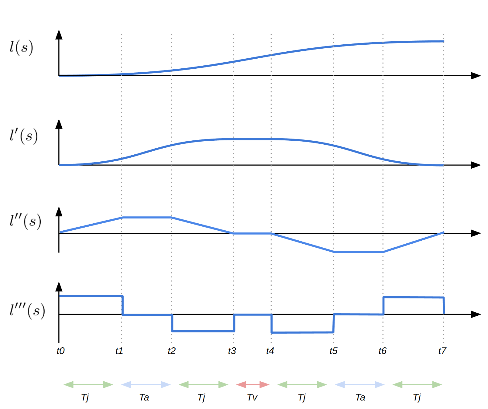
Starting from the initial longitudinal velocity of \(v_{0}^{\mathrm{lon}}\) and longitudinal acceleration of \(a^{\mathrm{lon}}\), at each time \(t_{1}, \cdots, t_{7}\), the lateral offset \(l_{i}\) at the corresponding longitudinal position \(s_{i}\)(with the longitudinal velocity \(v_{i}\)) is expressed as follows.
Given following inputs,
- desired longitudinal distance \(L_{\mathrm{lon}}\)
- desired lateral shift distance \(L\)
- longitudinal initial velocity \(v_{\mathrm{lon}}\)
- longitudinal acceleration \(a_{\mathrm{lon}}\)
- lateral acceleration limit \(a_{\mathrm{lim}}^{\mathrm{lat}}\)
shift internally computes
- total time of shift \(T_{\mathrm{total}}\)
- maximum lateral acceleration \(a_{\mathrm{max}}^{\mathrm{lat}}\) during the shift
- constant/zero jerk time \(T_{\mathrm{j}}, T_{\mathrm{a}}\) respectively
- required jerk \(j\)
as following
to obtain \((s_{i}, l_{i})\) respectively. Note that \(l_{7} == L\).
If \(a_{\mathrm{max}}^{\mathrm{lat}} > a_{\mathrm{lim}}^{\mathrm{lat}}\), then \(l_{i}\) is simply
Handling of duplicate points#
This package handles duplicate or almost-duplicate input points at two stages: when the trajectory bases are built from the raw points, and when each interpolator is constructed.
1. Base sanitisation in Trajectory<Point>::build#
Trajectory<Point>::build (and the derived builders that reuse it) converts the input point array into arc-length bases. Consecutive points whose 3D Euclidean distance is zero would produce identical bases, which breaks the strict monotonicity expected by later interpolation steps. To avoid this, the build step clamps every segment length to at least machine epsilon:
cpp
const auto dist = std::max<double>(
  autoware_utils_geometry::calc_distance3d(points.at(i), points.at(i - 1)),
  std::numeric_limits<double>::epsilon());
bases_.emplace_back(bases_.back() + dist);
This sanitisation preserves every input point; it only nudges the generated base coordinate enough to keep the base vector strictly increasing. The actual zero-division avoidance and stronger duplicate filtering are handled later by each interpolator's own build_impl.
TimeDistanceMapping::build applies the same idea to time bases as well. In the current implementation it also clamps each time increment to at least std::numeric_limits<double>::epsilon() before handing the bases to the interpolator.
2. Duplicate removal inside interpolator build_impl#
Most scalar interpolators (Linear, CubicSpline, AkimaSpline, and SphericalLinear) additionally remove true duplicates before they interpolate, as such duplicates can lead to numerical instability (e.g., division by very small intervals or ill-conditioned systems). Their build_impl functions call:
cpp
auto [cleaned_bases, cleaned_values] =
  ::autoware::experimental::trajectory::detail::remove_duplicate_points(bases, values, epsilon_);
remove_duplicate_points scans the bases from front to back and drops any point whose base difference from the last kept point is not larger than the interpolator's configured epsilon. The first point of a duplicate run is retained, the rest are discarded.
For the current default settings:
- spatial trajectory builders use
k_epsilon_distance - the internal time-to-distance
Linearinterpolator ofTemporalTrajectoryusesk_epsilon_time
3. Interpolators that do not deduplicate#
LaneIdsInterpolator and Stairstep do not invoke remove_duplicate_points; they operate on the bases exactly as provided by the trajectory build step. The base sanitisation described in stage 1 is therefore the only duplicate protection for these interpolators.
The is_almost_same helpers use quantity-specific thresholds:
- point / pose / path-point / trajectory-point position comparisons use
k_epsilon_distance - quaternion rotation comparison uses
k_epsilon_angle - temporal equality checks that are implemented explicitly in temporal utilities use
k_epsilon_time
Summary of thresholds#
| Stage | Threshold | Meaning |
|---|---|---|
| Spatial trajectory base construction | std::numeric_limits<double>::epsilon() |
Minimum base increment to keep arc-length bases increasing |
| Temporal time base construction | std::numeric_limits<double>::epsilon() |
Minimum base increment to keep time bases increasing |
| Spatial interpolator deduplication | k_epsilon_distance |
Spatial bases closer than this are treated as duplicates |
| Temporal interpolator deduplication | k_epsilon_time |
Time bases closer than this are treated as duplicates |
Geometric is_almost_same checks |
k_epsilon_distance |
Position-based equality threshold |
Quaternion is_almost_same checks |
k_epsilon_angle |
Rotation-equivalence threshold |