LiDAR Marker Localizer#
LiDARMarkerLocalizer is a detect-reflector-based localization node .
Inputs / Outputs#
lidar_marker_localizer node#
Input#
| Name | Type | Description |
|---|---|---|
~/input/lanelet2_map |
autoware_map_msgs::msg::HADMapBin |
Data of lanelet2 |
~/input/pointcloud |
sensor_msgs::msg::PointCloud2 |
PointType: PointXYZIRC is recommended in Autoware, but PointXYZIRADRT are also supported in this node.1 |
~/input/ekf_pose |
geometry_msgs::msg::PoseWithCovarianceStamped |
EKF Pose |
Output#
| Name | Type | Description |
|---|---|---|
~/output/pose_with_covariance |
geometry_msgs::msg::PoseWithCovarianceStamped |
Estimated pose |
/diagnostics |
diagnostic_msgs::msg::DiagnosticArray |
Diagnostics outputs |
For debug#
| Name | Type | Description |
|---|---|---|
~/debug/pose_with_covariance |
geometry_msgs::msg::PoseWithCovarianceStamped |
Estimated pose |
~/debug/marker_detected |
geometry_msgs::msg::PoseArray |
Detected marker poses |
~/debug/marker_mapped |
visualization_msgs::msg::MarkerArray |
Loaded landmarks to visualize in Rviz as thin boards |
~/debug/marker_pointcloud |
sensor_msgs::msg::PointCloud2 |
PointCloud of the detected marker |
~/debug/center_intensity_grid |
nav_msgs::msg::OccupancyGrid |
Center intensity grid for debug |
~/debug/positive_grid |
nav_msgs::msg::OccupancyGrid |
Positive match grid for debug |
~/debug/negative_grid |
nav_msgs::msg::OccupancyGrid |
Negative match grid for debug |
~/debug/matched_grid |
nav_msgs::msg::OccupancyGrid |
Matched pattern grid for debug |
~/debug/vote_grid |
nav_msgs::msg::OccupancyGrid |
Vote grid for marker detection debug |
Parameters#
| Name | Type | Description | Default | Range |
|---|---|---|---|---|
| enable_ |
boolean | true | N/A | |
| target_ |
array | List of target marker IDs to be detected. | ["0000", "0001", "0002", "0003", "0004", "0005"] | N/A |
| queue_ |
float | Queue size for output/pose_with_covariance publisher | 10 | ≥0 |
| marker_ |
string | The name of the markers listed in the HD map. | reflector | N/A |
| resolution | float | Grid size for marker detection algorithm. [m] | 0.05 | ≥0.0 |
| intensity_ |
array | A sequence of high/low intensity to perform pattern matching. 1: high intensity (positive match), 0: not consider, -1: low intensity (negative match) | [-1, -1, 0, 1, 1, 1, 1, 1, 0, -1, -1] | N/A |
| match_ |
float | Threshold for determining high/low. | 20 | ≥0 |
| positive_ |
float | Threshold for the number of required matches with the pattern. | 3 | ≥0 |
| negative_ |
float | Threshold for the number of required matches with the pattern. | 3 | ≥0 |
| vote_ |
float | Threshold for the number of rings matching the pattern needed to detect it as a marker. | 20 | ≥0 |
| marker_ |
float | Y-axis offset from the center of the marker to vehicle. [m] | 0.0 | N/A |
| marker_ |
float | Height from the ground to the center of the marker. [m] | 1.075 | N/A |
| lower_ |
float | Initial value when searching for the lowest ring ID within the point cloud | 128 | ≥0 |
| upper_ |
float | Initial value when searching for the highest ring ID within the point cloud | 0 | ≥0 |
| reference_ |
float | Reference ring number when detecting the marker. Set 255 to disable ring filtering | 255 | N/A |
| self_ |
float | Timeout for self pose. [sec] | 1.0 | ≥0.0 |
| self_ |
float | Tolerance for the distance between two points when performing linear interpolation. [m] | 1.0 | ≥0.0 |
| limit_ |
float | Distance limit for the purpose of determining whether the node should detect a marker. [m] | 2.0 | ≥0.0 |
| limit_ |
float | Y-axis distance limit for the purpose of determining whether the node should detect a marker. [m] | 1.0 | ≥0.0 |
| limit_ |
float | Distance limit for avoiding miss detection. [m] | 2.0 | ≥0.0 |
| base_ |
array | Output covariance in the base_link coordinate. | [0.04, 0.0, 0.0, 0.0, 0.0, 0.0, 0.0, 0.04, 0.0, 0.0, 0.0, 0.0, 0.0, 0.0, 0.01, 0.0, 0.0, 0.0, 0.0, 0.0, 0.0, 7.569e-05, 0.0, 0.0, 0.0, 0.0, 0.0, 0.0, 7.569e-05, 0.0, 0.0, 0.0, 0.0, 0.0, 0.0, 0.00030625] | N/A |
| marker_ |
float | Width of a marker. This param is used for visualizing the detected marker pointcloud[m] | 0.8 | ≥0.0 |
| enable_ |
boolean | false | N/A | |
| save_ |
string | $(env HOME)/ |
N/A | |
| save_ |
string | detected_ |
N/A | |
| save_ |
string | velodyne_ |
N/A | |
| radius_ |
float | Only points closer than this value to the marker center on the xy plane are extracted as the “marker point cloud”. [m] | 0.4 | ≥0.0 |
| queue_ |
float | Queue size for debug publishers | 10 | ≥0.0 |
How to launch#
When launching Autoware, set lidar-marker for pose_source.
ros2 launch autoware_launch ... \
    pose_source:=lidar-marker \
    ...
Design#
Flowchart#

Detection Algorithm#
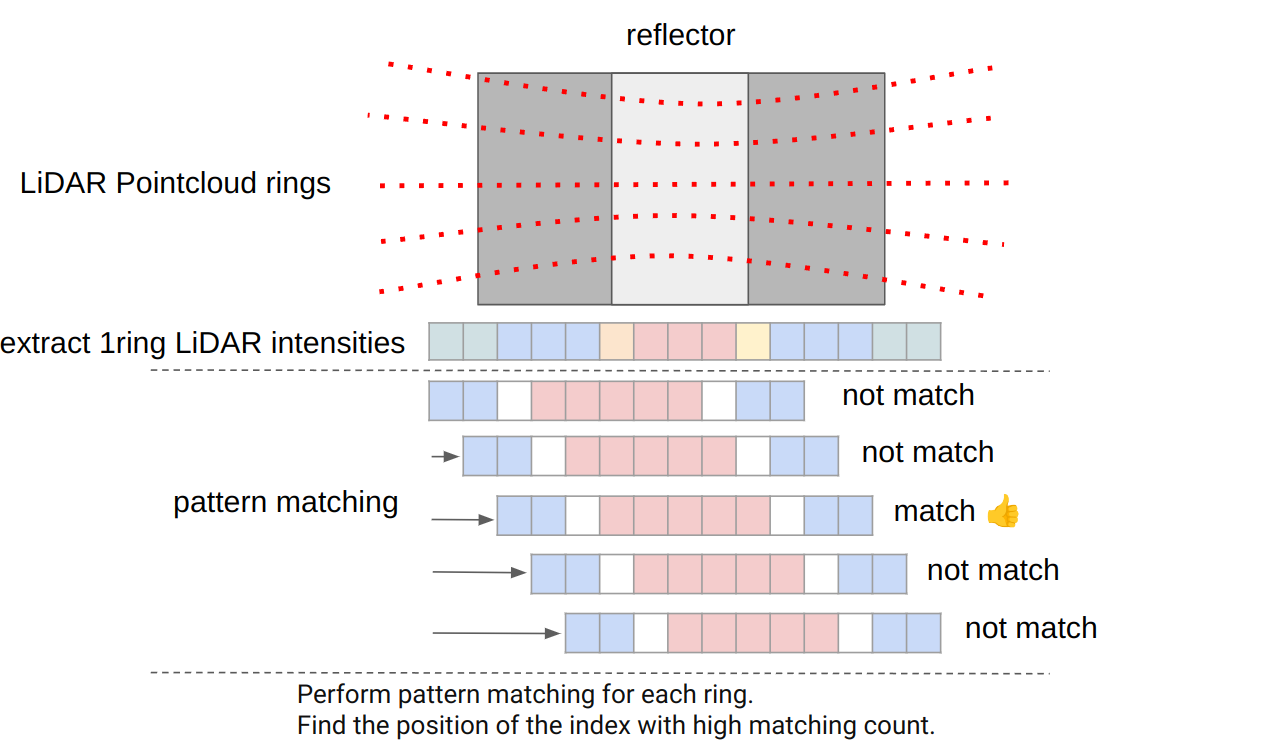
- Split the LiDAR point cloud into rings along the x-axis of the base_link coordinate system at intervals of the
resolutionsize. - Find the portion of intensity that matches the
intensity_pattern. - Perform steps 1 and 2 for each ring, accumulate the matching indices, and detect portions where the count exceeds the
vote_threshold_for_detect_markeras markers.
Sample Dataset#
This dataset was acquired in National Institute for Land and Infrastructure Management, Full-scale tunnel experiment facility. The reflectors were installed by Taisei Corporation.
Collaborators#
-
Assumed
ringofPointXYZIRADRTaschannelofPointXYZIRC. ↩