Vehicle Interface design#
Abstract#
The Vehicle Interface component provides an interface between Autoware and a vehicle that passes control signals to the vehicle’s drive-by-wire system and receives vehicle information that is passed back to Autoware.
1. Requirements#
Goals:
- The Vehicle Interface component converts Autoware commands to a vehicle-specific format and converts vehicle status in a vehicle-specific format to Autoware messages.
- The interface between Autoware and the Vehicle component is abstracted and independent of hardware.
- The interface is extensible such that additional vehicle-specific commands can be easily added. For example, headlight control.
Non-goals:
- Accuracy of responses from the vehicle will not be defined, but example accuracy requirements from reference designs are provided as examples.
- Response speed will not be defined.
2. Architecture#
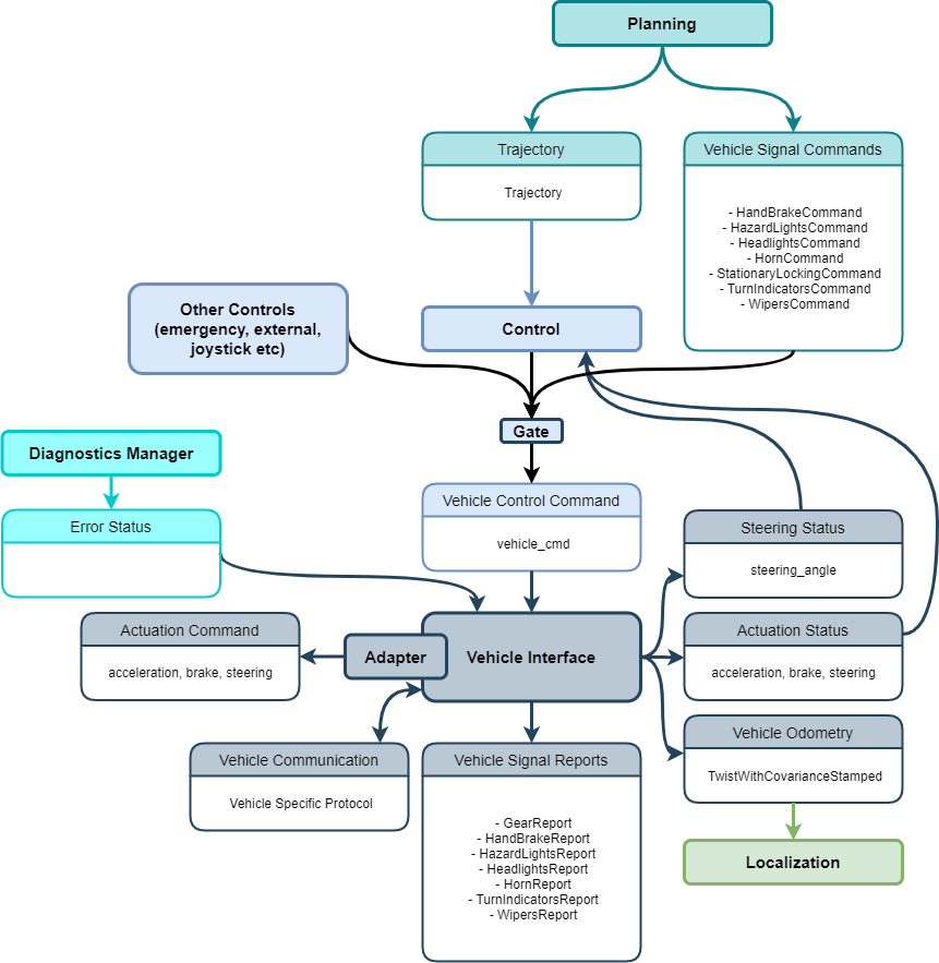
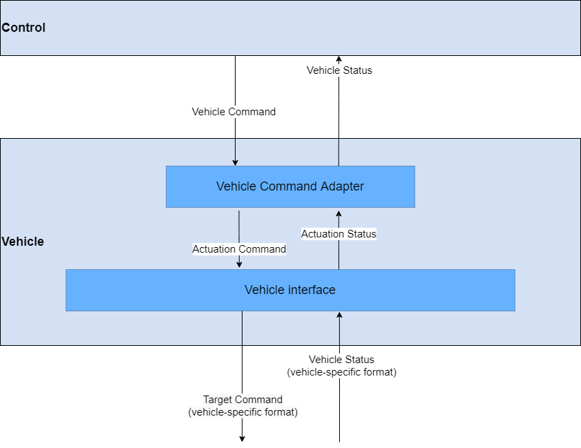
The Vehicle Interface component consists of the following components:
- A Raw Vehicle Command Converter component that will pass through vehicle commands from the Control component if velocity/acceleration control is supported by the drive-by-wire system. Otherwise, the Control commands will be modified according to the control method (eg: converting a target acceleration from the Control component to a vehicle specific accel/brake pedal value through the use of an acceleration map)
- A Vehicle Interface component (vehicle specific) that acts as an interface between Autoware and a vehicle to communicate control signals and to obtain information about the vehicle (steer output, tyre angle etc)
Each component contains static nodes of Autoware, while each module can be dynamically loaded and unloaded (corresponding to C++ classes). The mechanism of the Vehicle Interface component is depicted by the following figures:
3. Features#
The Vehicle Interface component can provide the following features in functionality and capability:
-
Basic functions
- Converting Autoware control commands to vehicle specific command
- Converting vehicle specific status information (velocity, steering) to Autoware status message
- Diagnostics
- List available features
- Provide a warning if the Control component tries to use a feature that is not available in the Vehicle Interface component
Additional functionality and capability features may be added, depending on the vehicle hardware. Some example features are listed below:
- Safety features
- Disengage autonomous driving via manual intervention.
- This can be done through the use of an emergency disengage button, or by a safety driver manually turning the steering wheel or pressing the brake
- Disengage autonomous driving via manual intervention.
- Optional controls
- Turn indicator
- Handbrake
- Headlights
- Hazard lights
- Doors
- Horn
- Wipers
4. Interface and Data Structure#
The interface of the Vehicle Interface component for other components running in the same process space to access the functionality and capability of the Vehicle Interface component is defined as follows.
From Control
- Actuation Command
- target acceleration, braking, and steering angle
From Planning
- Vehicle Specific Commands (optional and a separate message for each type)
- Shift
- Door
- Wiper
- etc
From the vehicle
- Vehicle status messages
- Vehicle-specific format messages for conversion into Autoware-specific format messages
- Velocity status
- Steering status (optional)
- Shift status (optional)
- Turn signal status (optional)
- Actuation status (optional)
- Vehicle-specific format messages for conversion into Autoware-specific format messages
The output interface of the Vehicle Interface component:
- Vehicle control messages to the vehicle
- Control signals to drive the vehicle
- Depends on the vehicle type/protocol, but should include steering and velocity commands at a minimum
- Vehicle status messages to Autoware
- Actuation Status
- Acceleration, brake, steering status
- Vehicle odometry (output to Localization)
- Vehicle twist information
- Control mode
- Information about whether the vehicle is under autonomous control or manual control
- Shift status (optional)
- Vehicle shift status
- Turn signal status (optional)
- Vehicle turn signal status
The data structure for the internal representation of semantics for the objects and trajectories used in the Vehicle Interface component is defined as follows:
5. Concerns, Assumptions, and Limitations#
Concerns
- Architectural trade-offs and scalability
Assumptions
-
Limitations