Creating a vehicle model for Autoware#
Introduction#
This page introduces the following packages for the vehicle model:
<YOUR-VEHICLE-NAME>_vehicle_description<YOUR-VEHICLE-NAME>_vehicle_launch
Previously,
we forked our vehicle model at the creating autoware repositories page step.
For instance,
we created tutorial_vehicle_launch
as an implementation example for the said step.
Please ensure that the
<YOUR-OWN-AUTOWARE-DIR>/
  └─ src/
       └─ vehicle/
            └─ <YOUR-VEHICLE-NAME>_vehicle_launch/
                 ├─ <YOUR-VEHICLE-NAME>_vehicle_description/
                 └─ <YOUR-VEHICLE-NAME>_vehicle_launch/
If your forked Autoware meta-repository doesn't include <YOUR-VEHICLE-NAME>_vehicle_launch with the correct folder structure
as shown above,
please add your forked <YOUR-VEHICLE-NAME>_vehicle_launch repository to the autoware.repos file
and run the vcs import src < autoware.repos command in your terminal
to import the newly included repositories at autoware.repos file.
Now, we are ready to modify the following vehicle model packages for our vehicle. Firstly, we need to rename the description and launch packages:
<YOUR-VEHICLE-NAME>_vehicle_launch/
- ├─ sample_vehicle_description/
+ ├─ <YOUR-VEHICLE-NAME>_vehicle_description/
- └─ sample_vehicle_launch/
+ └─ <YOUR-VEHICLE-NAME>_vehicle_launch/
After that, we will change our package names in the package.xml file and CMakeLists.txt file of the sample_vehicle_description and sample_vehicle_launch packages. So, open the package.xml file and CMakeLists.txt file with any text editor or IDE of your preference and perform the following changes:
Change the <name> attribute at package.xml file:
<package format="3">
- <name>sample_vehicle_description</name>
+ <name><YOUR-VEHICLE-NAME>_vehicle_description</name>
  <version>0.1.0</version>
  <description>The vehicle_description package</description>
  ...
  ...
Change the project() method at CmakeList.txt file.
  cmake_minimum_required(VERSION 3.5)
- project(sample_vehicle_description)
+ project(<YOUR-VEHICLE-NAME>_vehicle_description)

  find_package(ament_cmake_auto REQUIRED)
...
...
Remember to apply the name changes and project method for BOTH
<YOUR-VEHICLE-NAME>_vehicle_descriptionand <YOUR-VEHICLE-NAME>_vehicle_launch ROS 2 packages.
Once finished, we can proceed to build said packages:
colcon build --symlink-install --cmake-args -DCMAKE_BUILD_TYPE=Release --packages-up-to <YOUR-VEHICLE-NAME>_vehicle_description <YOUR-VEHICLE-NAME>_vehicle_launch
Vehicle description#
The main purpose of this package is to describe the vehicle dimensions, 3D model of the vehicle, mirror_dimensions of the vehicle, simulator model parameters and URDF of the vehicle.
The folder structure of vehicle_description package is:
<YOUR-VEHICLE-NAME>_vehicle_description/
   ├─ config/
   │     ├─ mirror.param.yaml
   │     ├─ simulator_model.param.yaml
   │     └─ vehicle_info.param.yaml
   ├─ mesh/
   │     ├─ <YOUR-VEHICLE-MESH-FILE>.dae (or .fbx)
   │     ├─ ...
   └─ urdf/
         └─ vehicle.xacro
Now, we will modify these files according to our vehicle design.
mirror.param.yaml#
This file describes your vehicle mirror dimension for CropBox filter of PointCloudPreprocessor. This is important for cropping mirrors from your lidar's point cloud.
The mirror.param.yaml consist of the following parameters:
/**:
  ros__parameters:
    min_longitudinal_offset: 0.0
    max_longitudinal_offset: 0.0
    min_lateral_offset: 0.0
    max_lateral_offset: 0.0
    min_height_offset: 0.0
    max_height_offset: 0.0
The mirror param file should be filled with this dimension information,
please be careful with min_lateral_offsetparameter,
it could be negative value like the mirror dimension figure below.

Warning
Since there is no mirror in tutorial_vehicle, all values set to 0.0.
If your vehicle does not have mirror, you can set these values 0.0 as well.
simulator_model.param.yaml#
This file is a configuration file for the simulator environment. Please update these parameters according to your vehicle specifications. For detailed information about variables, please check the simple_planning_simulator package. The file consists of these parameters:
/**:
  ros__parameters:
    simulated_frame_id: "base_link" # center of the rear axle.
    origin_frame_id: "map"
    vehicle_model_type: "DELAY_STEER_ACC_GEARED" # options: IDEAL_STEER_VEL / IDEAL_STEER_ACC / IDEAL_STEER_ACC_GEARED / DELAY_STEER_ACC / DELAY_STEER_ACC_GEARED
    initialize_source: "INITIAL_POSE_TOPIC" #  options: ORIGIN / INITIAL_POSE_TOPIC
    timer_sampling_time_ms: 25
    add_measurement_noise: False # the Gaussian noise is added to the simulated results
    vel_lim: 50.0 # limit of velocity
    vel_rate_lim: 7.0 # limit of acceleration
    steer_lim: 1.0 # limit of steering angle
    steer_rate_lim: 5.0 # limit of steering angle change rate
    acc_time_delay: 0.1 # dead time for the acceleration input
    acc_time_constant: 0.1 # time constant of the 1st-order acceleration dynamics
    steer_time_delay: 0.24 # dead time for the steering input
    steer_time_constant: 0.27 # time constant of the 1st-order steering dynamics
    x_stddev: 0.0001 # x standard deviation for dummy covariance in map coordinate
    y_stddev: 0.0001 # y standard deviation for dummy covariance in map coordinate
vehicle_info.param.yaml#
This file stores the vehicle dimensions for Autoware modules.
Please update it with your vehicle information.
You can refer to the vehicle dimensions page for detailed dimension demonstration.
Here is the vehicle_info.param.yaml for sample_vehicle:
/**:
  ros__parameters:
    wheel_radius: 0.383 # The radius of the wheel, primarily used for dead reckoning.
    wheel_width: 0.235 # The lateral width of a wheel tire, primarily used for dead reckoning.
    wheel_base: 2.79 # between front wheel center and rear wheel center
    wheel_tread: 1.64 # between left wheel center and right wheel center
    front_overhang: 1.0 # between front wheel center and vehicle front
    rear_overhang: 1.1 # between rear wheel center and vehicle rear
    left_overhang: 0.128 # between left wheel center and vehicle left
    right_overhang: 0.128 # between right wheel center and vehicle right
    vehicle_height: 2.5
    max_steer_angle: 0.70 # [rad]
Please update vehicle_info.param.yaml with your vehicle information.
3D model of vehicle#
You can use .fbx or .dae format as a 3D model with autoware.
For the tutorial_vehicle,
we exported our 3D model as a .fbx file in the tutorial_vehicle_launch repository.
We will set the .fbx file path at vehicle.xacro file.
vehicle.xacro#
This .xacro file links the base_link of the vehicle to the 3D mesh. Therefore, we need to make some modifications in this file.
<?xml version="1.0"?>
<robot xmlns:xacro="http://ros.org/wiki/xacro">
  <!-- load parameter -->
- <xacro:property name="vehicle_info" value="${xacro.load_yaml('$(find sample_vehicle_description)/config/vehicle_info.param.yaml')}"/>
+ <xacro:property name="vehicle_info" value="${xacro.load_yaml('$(find <YOUR-VEHICLE-NAME>_vehicle_description)/config/vehicle_info.param.yaml')}"/>

  <!-- vehicle body -->
  <link name="base_link">
    <visual>
      <origin xyz="${vehicle_info['/**']['ros__parameters']['wheel_base']/2.0} 0 0" rpy="${pi/2.0} 0 ${pi}"/>
      <geometry>
-       <mesh filename="package://sample_vehicle_description/mesh/lexus.dae" scale="1 1 1"/>
+       <mesh filename="package://<YOUR-VEHICLE-NAME>_vehicle_description/mesh/<YOUR-3D-MESH-FILE>" scale="1 1 1"/>
      </geometry>
    </visual>
  </link>
</robot>
You can also modify roll, pitch, yaw, x, y, z and scale values for the correct position and orientation of the vehicle.
Please build vehicle_description package after the completion of your
cd <YOUR-AUTOWARE-DIR>
colcon build --symlink-install --cmake-args -DCMAKE_BUILD_TYPE=Release --packages-up-to <YOUR-VEHICLE-NAME>_vehicle_description <YOUR-VEHICLE-NAME>_vehicle_launch
Launching vehicle interface#
If your vehicle interface is ready,
then you can add your vehicle_interface launch file in vehicle_interface.launch.xml.
Please check the creating vehicle interface page for more info.
Launch planning simulator with your own vehicle#
After completing the sensor_model, individual_parameters and vehicle model of your vehicle, you are ready to launch the planning simulator with your own vehicle. If you are not sure if every custom package in your Autoware project folder is built, please build all packages:
cd <YOUR-AUTOWARE-DIR>
colcon build --symlink-install --cmake-args -DCMAKE_BUILD_TYPE=Release
To launch the planning simulator, source the install/setup.bash file in your Autoware project folder and run this command in your terminal:
ros2 launch autoware_launch planning_simulator.launch.xml map_path:=$HOME/Files/autoware_map/sample-map-planning/ vehicle_model:=<YOUR-VEHICLE-MODEL> sensor_model:=<YOUR-SENSOR-KIT> vehicle_id:=<YOUR-VEHICLE-ID>
For example, if we try planning simulator with the tutorial_vehicle:
ros2 launch autoware_launch planning_simulator.launch.xml map_path:=$HOME/Files/autoware_map/sample-map-planning/ vehicle_model:=tutorial_vehicle sensor_model:=tutorial_vehicle_sensor_kit vehicle_id:=tutorial_vehicle
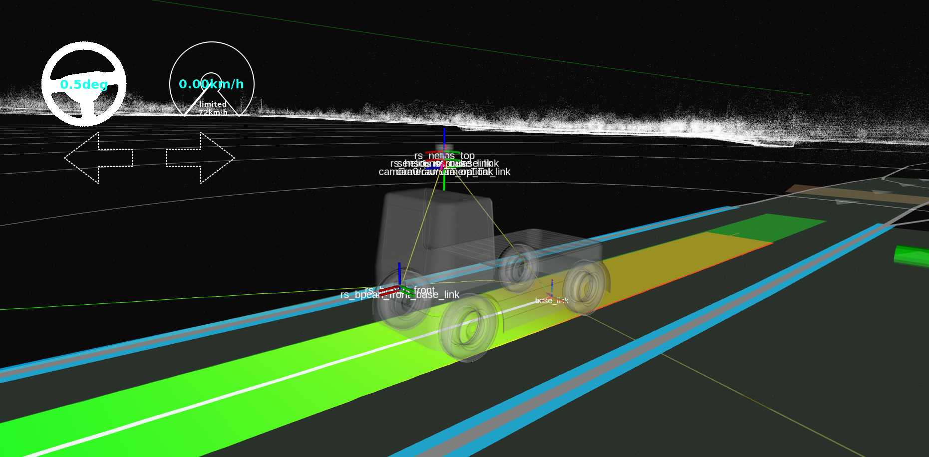
The planning simulator will open, and you can give an initial pose to your vehicle
using 2D Pose Estimate button or by pressing the P key on your keyboard.
You can click everywhere for vehicle initialization.